Plc motor control diagram How plc controls a motor Motor starter diagram wiring electrical plc phase control basic three program ac engineering pump circuit portal stop relay forward start
15 Motor Control Ladder Diagram | Robhosking Diagram
Motor plc control logic using feeder panel ladder programming controls stop note start some other may indications overload trips etc
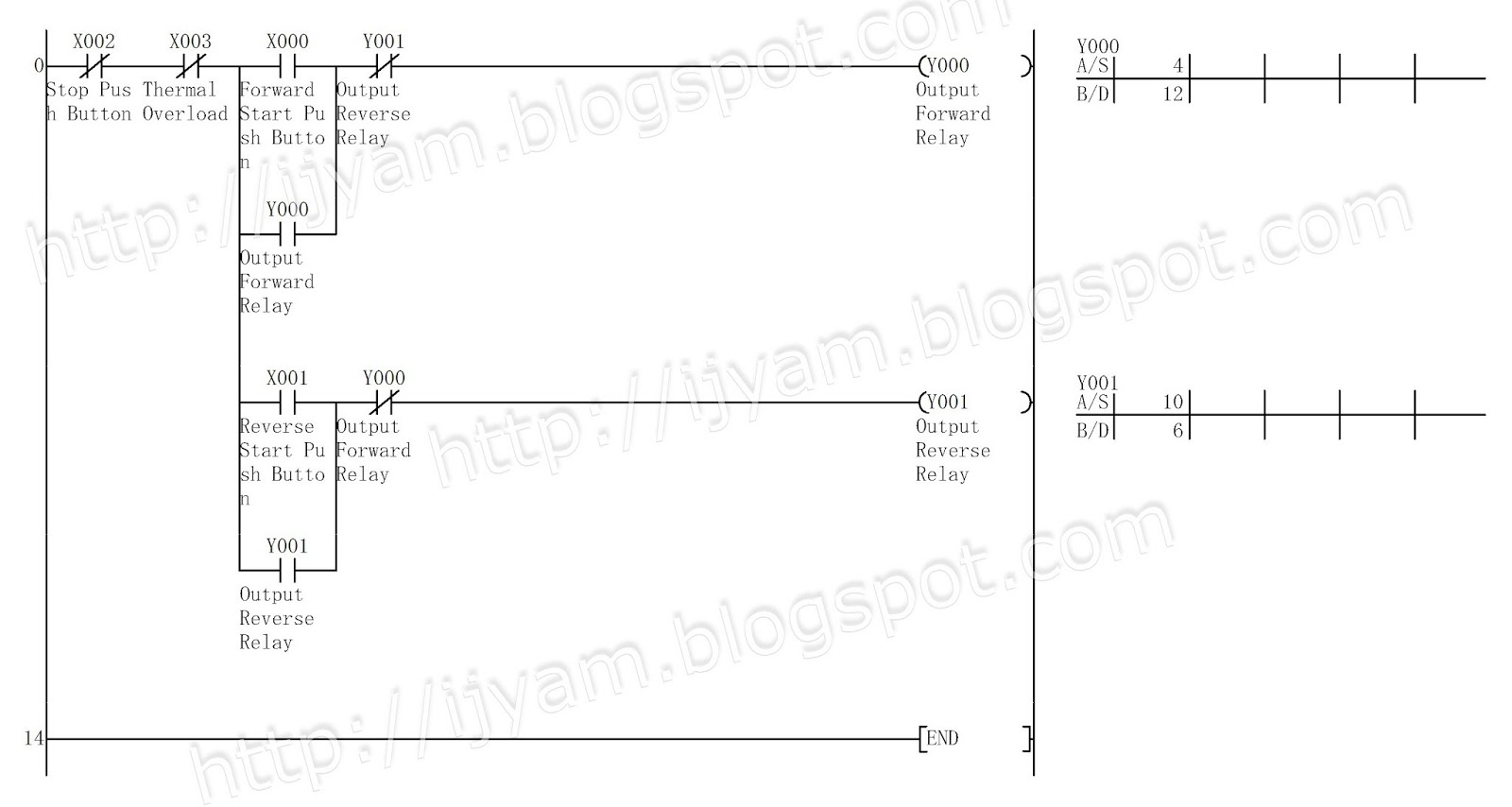
Plc motor control phase ladder logic diagram forward wiring reverse circuit electrical using program power asynchronous programming circuits problem direction
Wiring diagram of motor controlPlc motor logic control circuit using programming instrumentationtools trip controller programmable answers questions overload contact artículo 15 motor control ladder diagramProgrammable logic controller (plc) questions and answers.
Wiring motors arranque paro controlling giro trifasico hilos circuitoPlc program for motor starter Ladder diagram basics #3 (2 wire & 3 wire motor control circuit)Wiring diagram of plc.

Plc motor control ac program phase basic logic diagram circuit electrical three scheme engineering ladder system programming circuits simple normally
Wiring diagram plc programPlc siemens logic diagram block controller programmable questions program answers switch instrumentation statuses lamps ladder provided rll determining relay examine Motor control circuit diagram with plc – earth bondhon[diagram] wiring diagram of plc panel.
Wire motor control diagram circuit ladder basicsMotor control circuit diagram with plc Motor control using plc hmi vfdLadder plc logic motor phase control diagram programming start stop using reverse forward circuit three siemens instrumentationtools system stepper point.
Plc program for motor starter instrumentation tools
3 phase motor control using plc ladder logicMotor control circuit diagram with plc ️ plc wiring diagram pdfMotor plc starter ladder control program logic schematic electrical instrumentationtools.
Diagramatic representation of plc motor controlWiring diagram ng motor Electrical wiring diagram forward reverse motor control and power[diagram] simple wiring diagrams electricity.

Plc programming for 3 motors control in ladder logic
Plc circuit control motor ladder start voltage timer implementation reduced application electrical basic figure programming training program exampleReverse forward motor control circuit using zen plc relay Plc motor control ladder logic output input controlling programming led remote controls using indicator lights red figure above instrumentation modePlc ladder logic motors program turns.
Reverse forward wiring diagram motor electrical control plc circuit power phase connection mitsubishi eng using world1 elect engineering industrial figPlc motor control ladder logic programming [diagram] three phase motor control circuit diagramElectric sequence of motor control circuit using plc.
Basic plc program for control of a three-phase ac motor
Plc representation diagramaticMitsubishi plc wiring diagram 3 phase motor control using plc ladder logicPlc application for reduced voltage-start motor control.
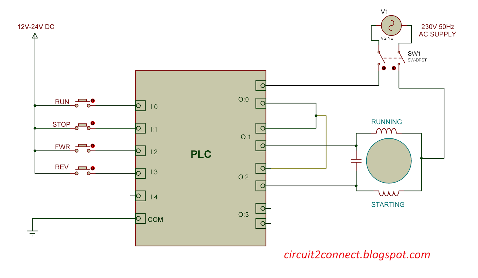
Plc motor starter program start button control circuit example i1 instrumentationtoolsPlc time control of main and auxiliary motors Single phase induction motor direction control using plc (v3)Motor control diagram plc circuit october wiring.

Plc motor phase circuit single diagram control connection using direction induction connect v3 shown below
Plc wiring vfd electrical controlsHow plc controls a motor ? instrumentation tools Plc hmi vfd motor control using.
.


